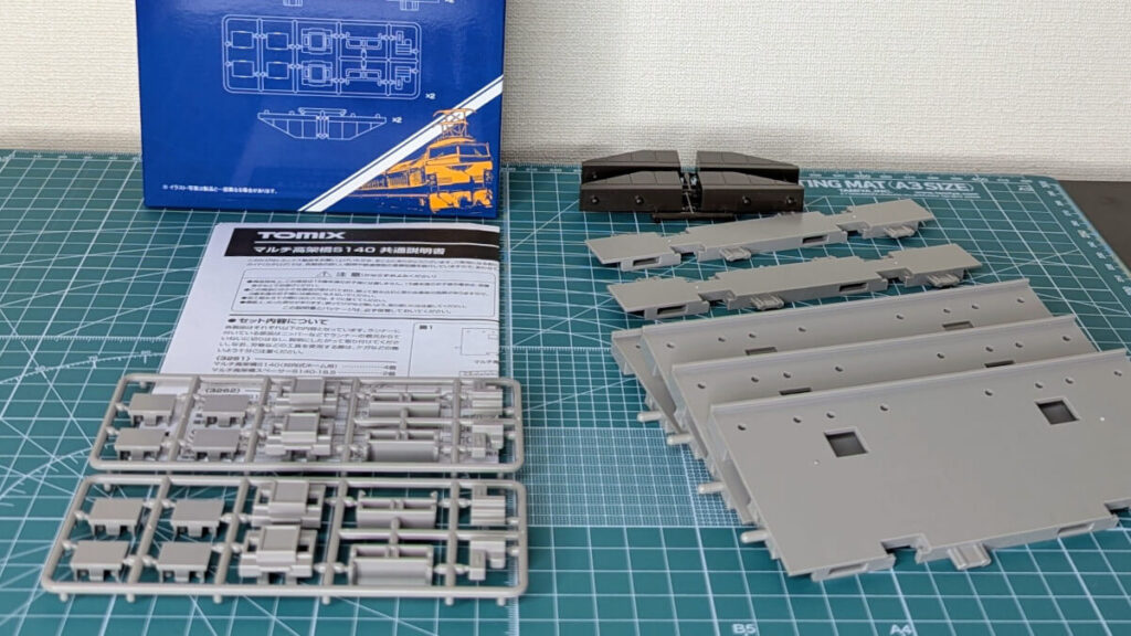
This time, we used a multi-viaduct from TOMIX to create an elevated station with three platforms and four tracks, modeled after Nankai Electric Railway's Shin-Imamiya Station. The products used are as follows:
- (3235) PC horizontal pier P10 (set of 8)
- (3244) Multi-level Elevated Beam, Medium (4 pieces)
- (3261) Multi-Viaduct S140 (for opposing platforms) (2 sets)
- (3263) Multi-Viaduct Spacer S140 (4 pairs)
Now, let me introduce the actual process and work involved.
(3235) PC horizontal pier P10 (set of 8)
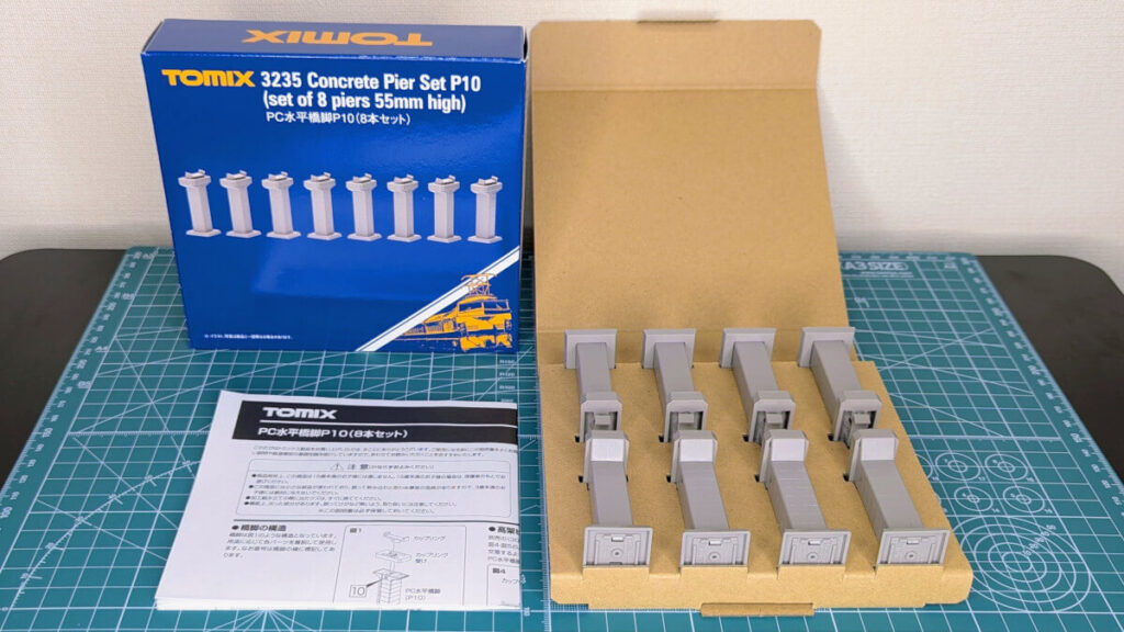
The pier consists of three parts:
- Coupling
- Coupling holder
- PC horizontal pier
Dismantle the bridge pier
In order to attach the parts included with the "Story Elevated Beam" to the pier, first remove and disassemble each part. Disassembly can be done by simply pulling it out by hand, but it requires some force.
Although we will use "couplings" later, we will not use "coupling receivers" in this example. Instead, the "story elevated beam" will play the role of coupling receivers.
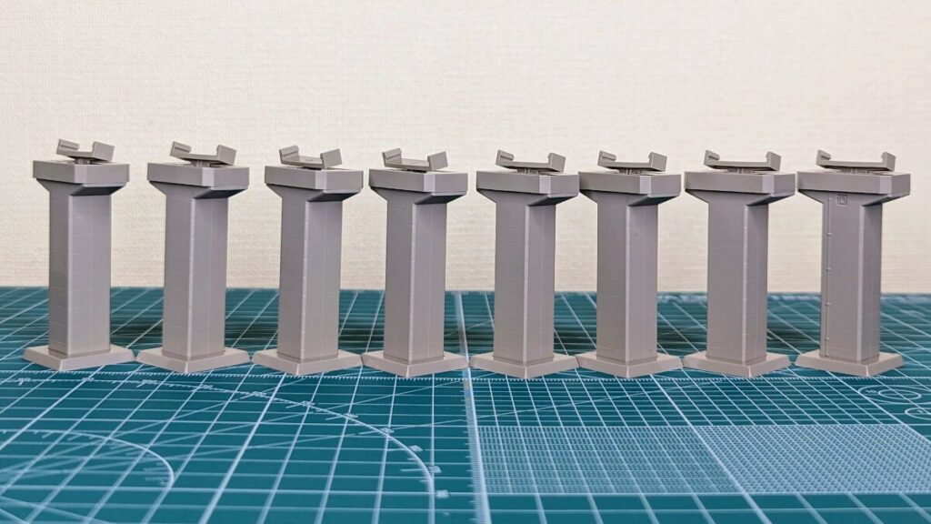
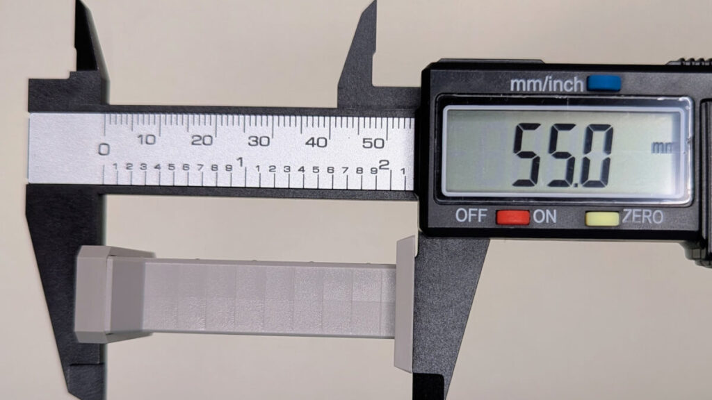
For reference, I measured
I measured the height of the pier before removing the "coupling support" from the pier. It was exactly as stated in the catalog, showing the high level of precision you'd expect from Tomix.
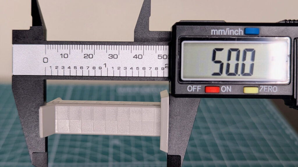
The coupling support has been removed from the pier. This time, we will continue working on the bridge in this state.
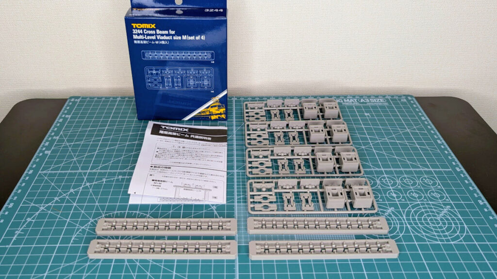
(3244) Multi-level Elevated Beam, Medium (4 pieces)
There are two types of floor overhead beams, M and L. M has 11 part mounting holes and L has 13. In this example, L is not long enough, so two M beams will be used.
Set contents
- Floor Elevated Beam x 4
- Common runner parts x 4 runners
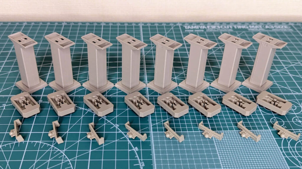
Pier adapter installation
Use pliers to separate the "pier adapter" from the runner.
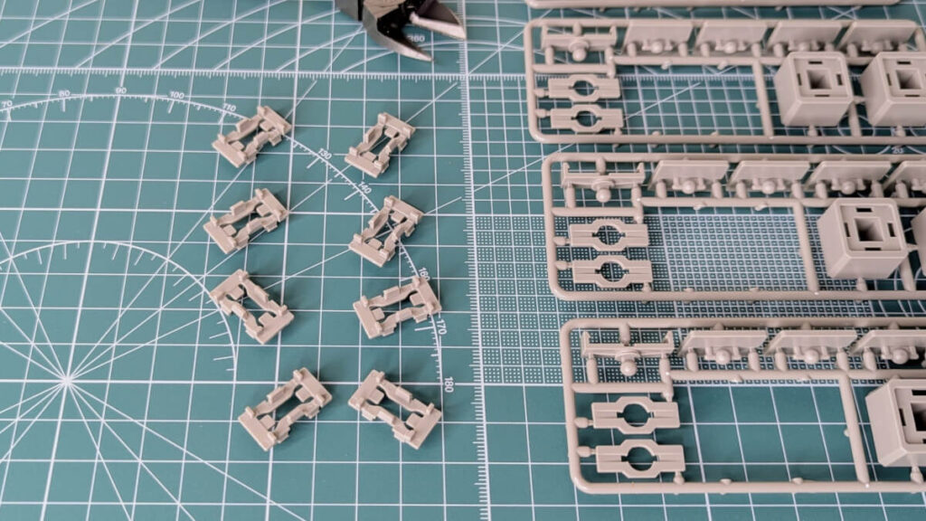
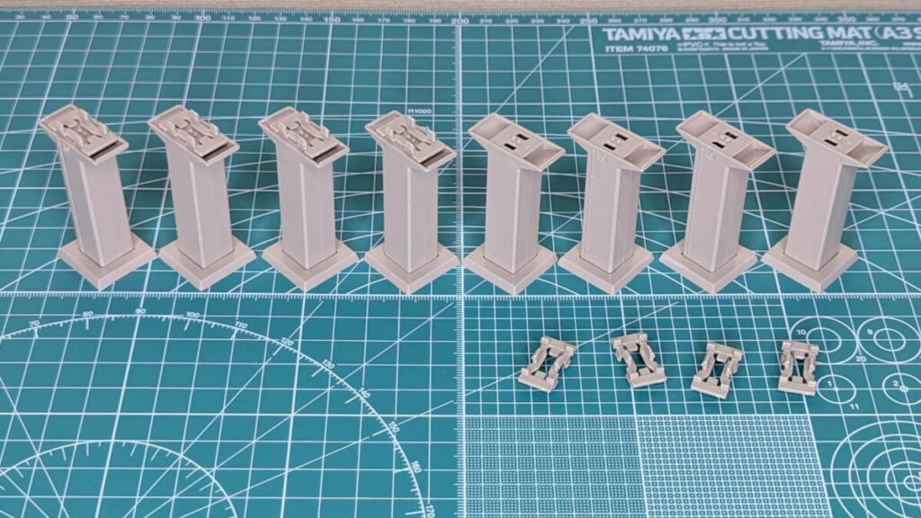
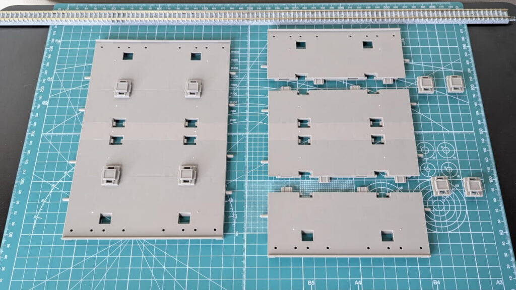
Attach the "pier adapters" to the disassembled piers. The four on the right are before installation, and the four on the left are after installation.
Installing hole filling parts
In this example, the mounting holes for the elevated beams are visible, so we will cover them with "hole filling parts."
Use pliers to cut the "filler parts" off from the runner.
The "hole filling parts" and the piers with pier adapters are attached to the elevated beams. The two at the back are the state after installation.
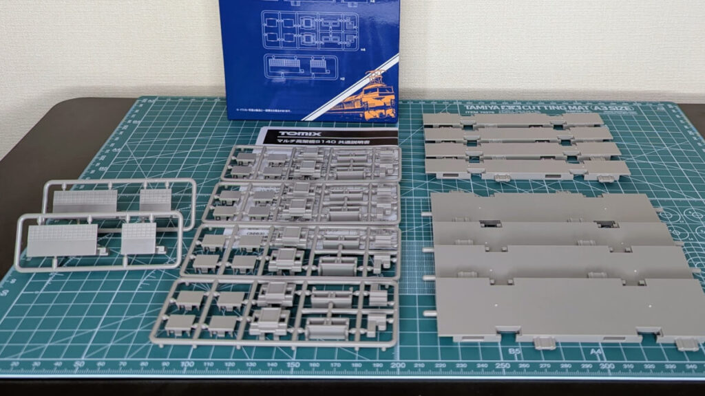
(3261) Multi-Viaduct S140 (for opposing platforms) (2 sets)
By combining multiple viaducts, it is possible to create various types of elevated stations, such as one platform with two tracks or two platforms with four tracks.
Set contents
- Multi-viaduct S140 (for opposing platforms) x 4
- Multi-viaduct spacer S140-18.5 x 2
- Hole filling and rail fixing parts x 2 runners
- External staircase parts (A and B) x 2 runners
In this example, we will only be using the "Multi Viaduct S140 (for opposing platforms)" shown in the bottom right of the image. It will be used in combination with other spacers, which will be introduced next.
(3263) Multi-Viaduct Spacer S140 (4 pairs)
The spacers are available in two widths, one for island platforms and one for rails.
Set contents
- Multi-viaduct spacer S140-37 x 4
- Multi-viaduct spacer S140-18.5 x 4 pieces
- Hole filling and rail fixing parts x 4 runners
- End wall part B x 2 runner
Assembling the spacer
In this example, we will combine a spacer for an island platform (18.5mm) with a spacer for rails (37mm) sandwiched between them on both sides.
The spacers must be firmly pressed in, aligning the convex and concave parts so that there are no gaps. The right side shows the state before assembly, and the left side shows the state after assembly.
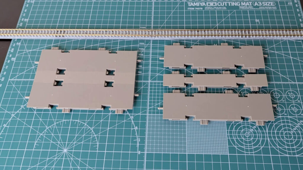
Installation requires some force, so please work carefully to avoid damaging the parts.
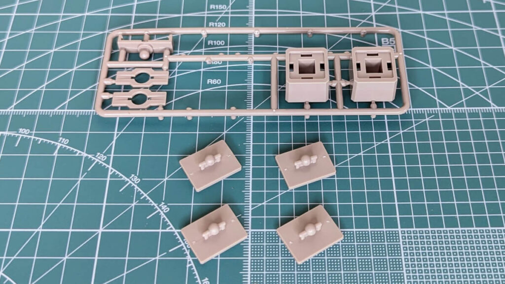
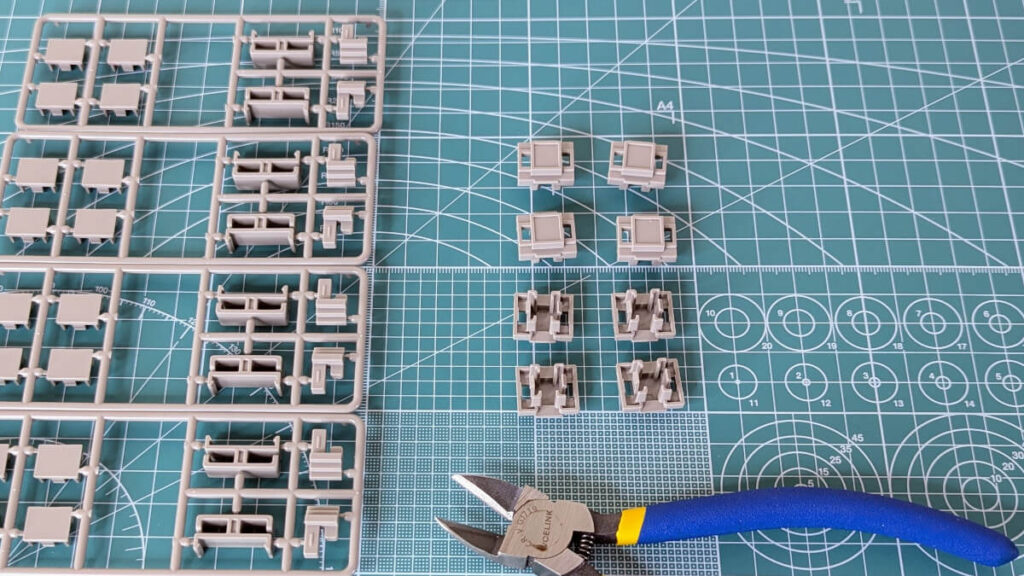
Installing the rail fixing parts
The "rail fixing parts" are parts used to maintain the double track spacing (37mm) on Tomix N gauge rails.
Use pliers to separate the "rail fixing parts" from the runner. The top four are the front side, and the bottom four are the back side.
After combining the "Multi Viaduct S140 (for opposing platforms)" with the spacer we just assembled, we attach the "rail fixing parts." The right side shows the state before installation, and the left side shows the state after installation.
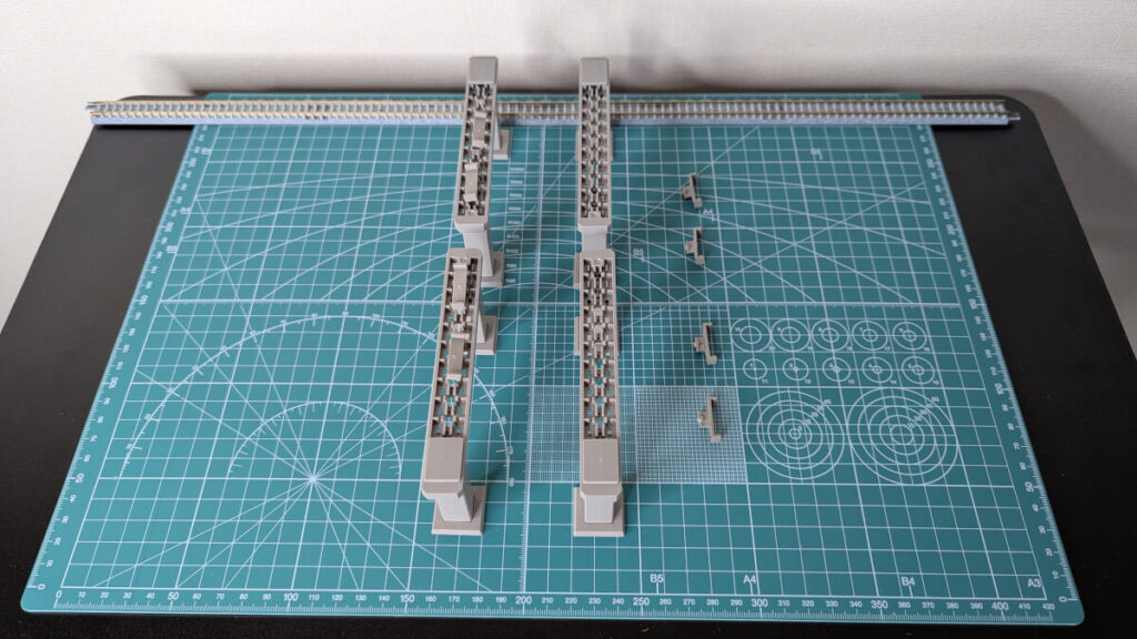
Viaduct assembly
Attach the disassembled pier "couplings" to the elevated beams. The two on the right are before installation, and the two on the left are after installation.
The side with the "hole filler part" attached will be on the outside, as shown in the image.
The installation position of the "coupling" is determined according to the position where the "Multi Viaduct Spacer S140-37" will be received. It differs depending on the type of viaduct you are constructing.
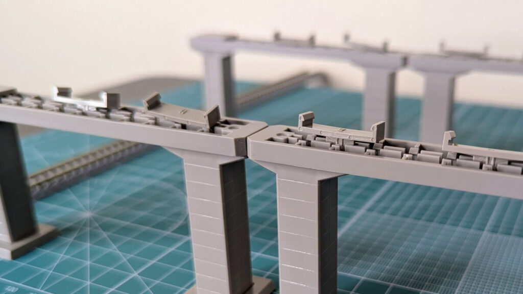
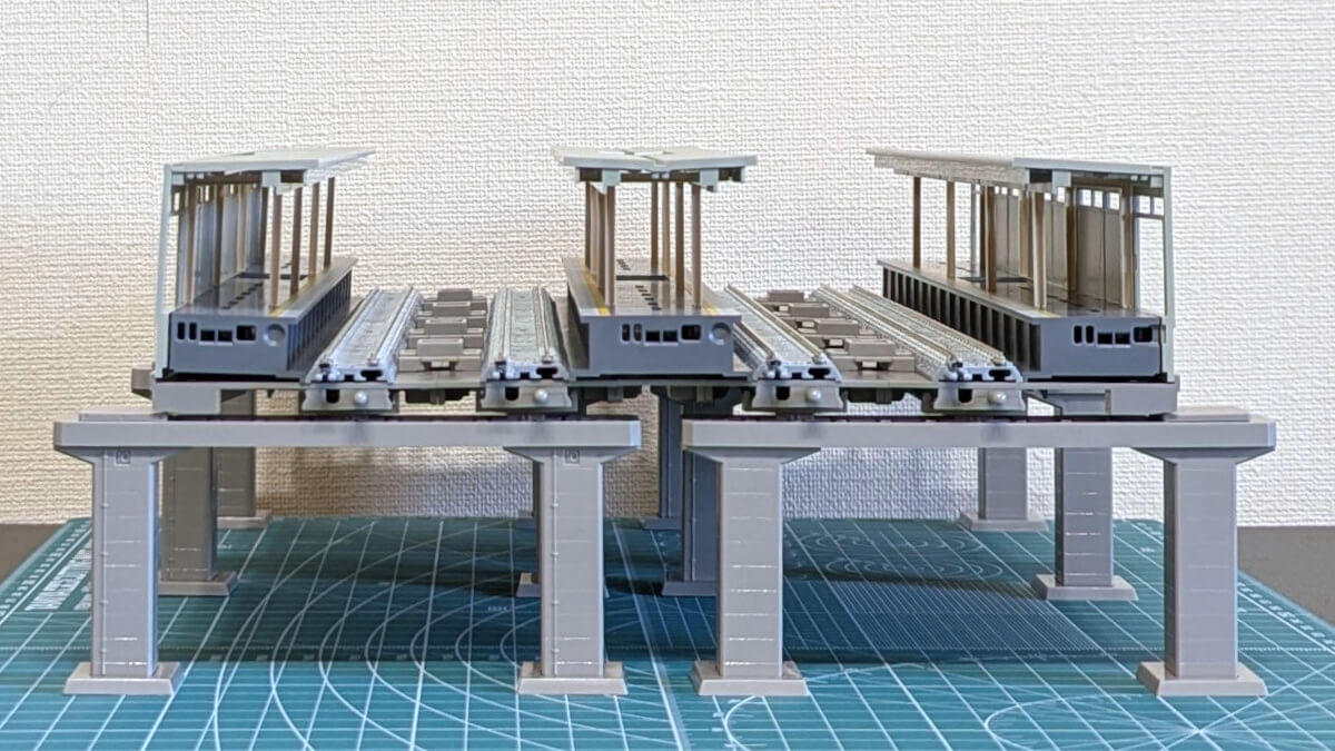
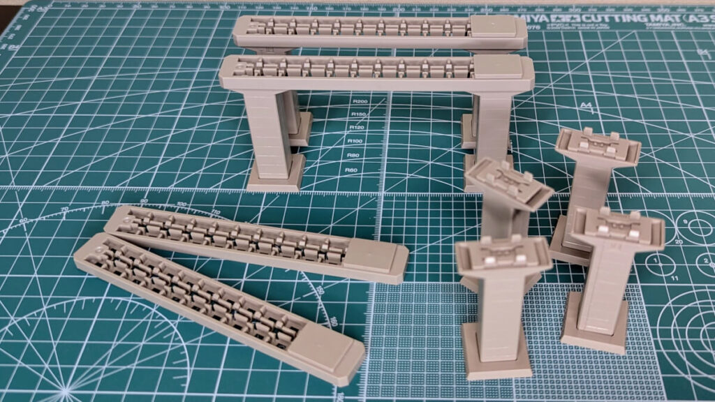
Combine two sets of multi-viaducts (S140 x 2) and attach the piers at 140mm intervals. Simply lightly press the spacers in to fit them in place.
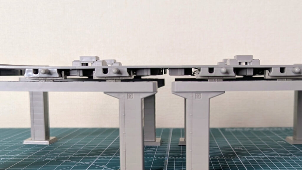
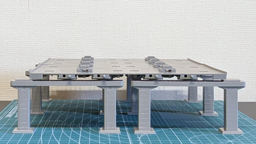
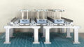
Once the platform and rails are placed, it's complete. It fits surprisingly perfectly, and you can really feel the high level of precision.