How to use Pepakura Designer
What is Pepakura Designer?
Pepakura Designer is software for converting 3D models into paper development diagrams. Developed by the Japanese software development company Tamasoft, Pepakura Designer automatically decomposes the 3D shape by simply importing 3D data, and creates a development diagram that can be assembled on paper.
By exporting the unfolded diagram as vector data such as DXF, it can also be used to create architectural models and model parts, making it a software that is widely used for everything from hobby model making to educational purposes and professional model making.
Installing Pepakura Designer
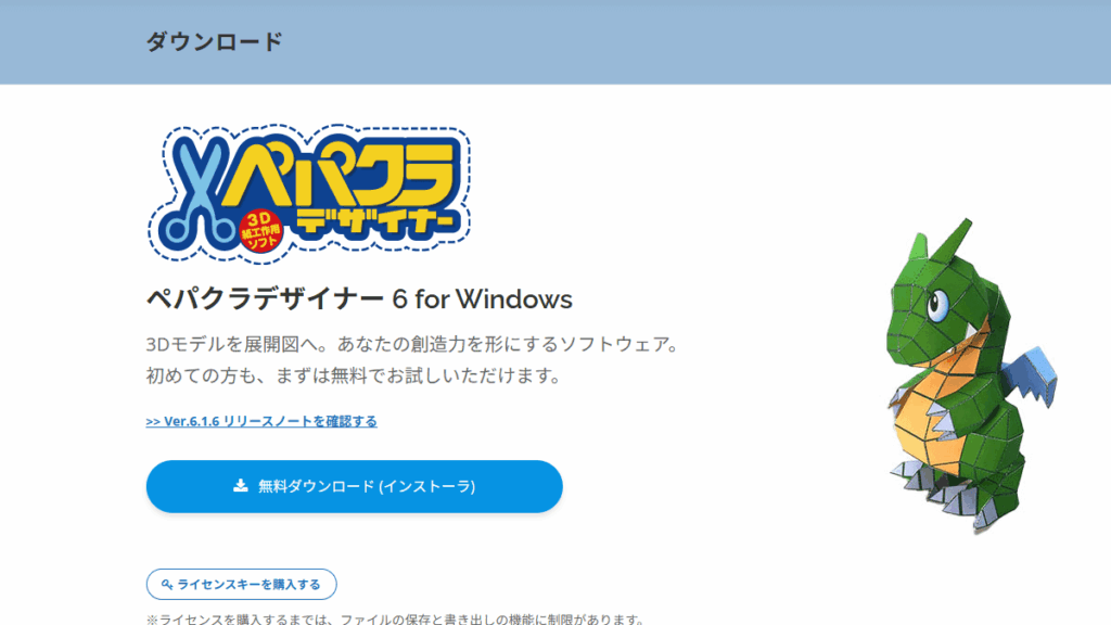
Download Pepakura Designer
- Official websiteOpen
- Click the "Free Download (Installer)" button on the screen.
Installing Pepakura Designer
- Run (double-click) the downloaded file (setup_pepakura***.exe).
- Follow the on-screen instructions to proceed with the installation
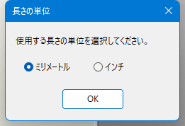
- After the installation is complete, Pepakura Designer will start.
- Please choose the "unit of length" that is easy for you to understand.
Importing 3D models
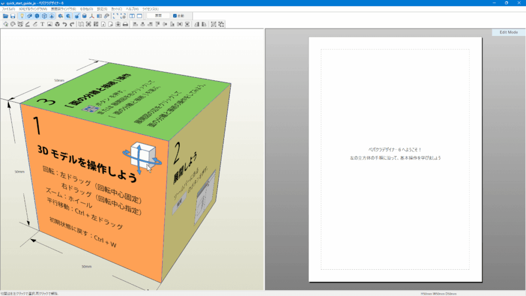
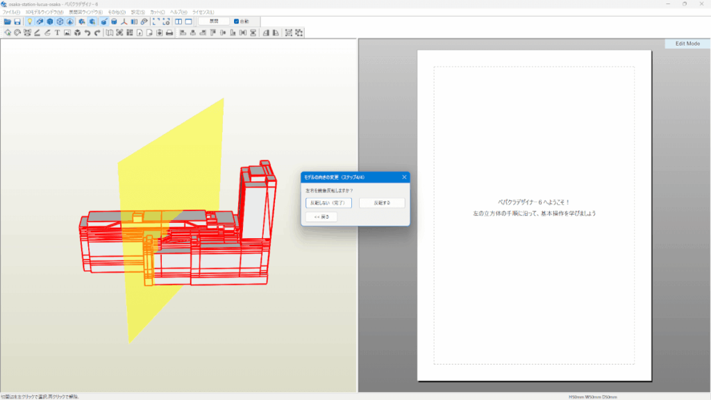
Once Pepakura Designer is installed, a sample cube model will be displayed. This is a tutorial to help you learn how to use it, so we won't use it this time. From here, load the OBJ file (Lucua Osaka) exported from Blender.
Importing OBJ
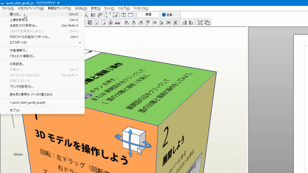
Click "File" in the top menu and select "Open." In the file selection dialog, select the OBJ file you exported in Blender.
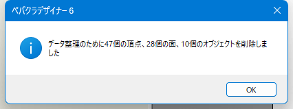
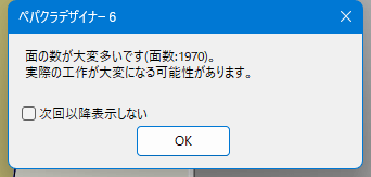
Several confirmation dialogs will appear, so check the contents and click the "OK" button.
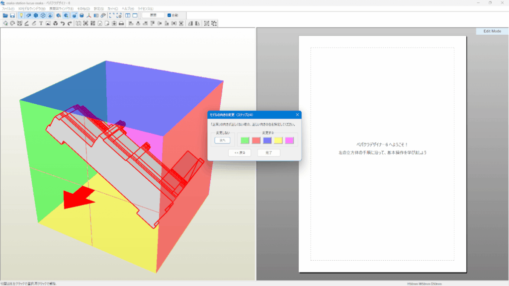
Changing the orientation of a model
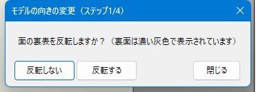
Four confirmation items will be displayed, so set each one.
Front and back of the face
In this case:
- Plateau
- Blender
- OBJ
For OBJs created in this way, select "Do not flip."
Specify the "front" orientation
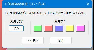
For architectural models, the front of the building (the facade side that people see) should be the front. The front (building entrance) or the top (roof) is the easiest to unfold.
Specify the orientation of the "bottom"
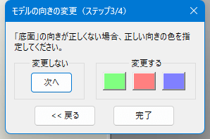
In this case, the orientation of the bottom is correct, so click "Do not change (Next)."
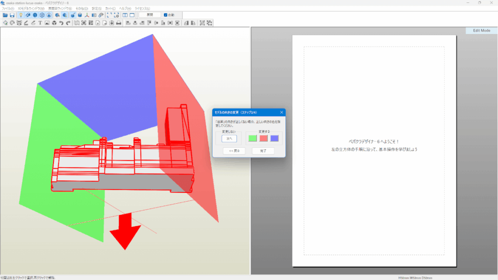
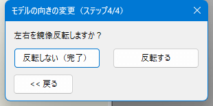
Mirror image left and right
In this case:
- Plateau
- Blender
- OBJ
For OBJs created using this method, the left and right orientation is usually set correctly. Flipping may be necessary if, for example, the building is displayed upside down. Therefore, click "Do not flip (Done)" here.
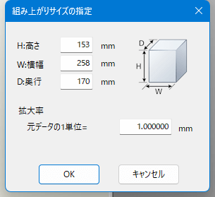
Specifying assembled size
Next, set the size of the completed model. The default values are as follows:
To accurately set the "Assembled Size Specification", first obtain the actual height of the building and convert that value to a 1/150 scale. In Google Earth, the height of a building is displayed as the elevation of the cursor position, so the height is calculated using the difference in elevation between the top of the building and the ground.
Measure building heights with Google Earth
Measure the building in question in Google Earth. When you hover the mouse cursor over the top of the building, "152m" will be displayed.
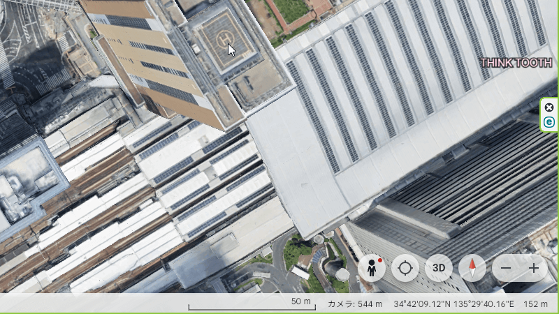
On the other hand, if you move the mouse cursor over the sidewalk right next to the building, the message "-21cm" will be displayed.

First, we need to align the units. "-21cm" on the sidewalk is "-0.21m" in meters. Therefore, the height of the building is:
152 − (−0.21) = 152.21mThis is the actual building height.
Convert height to 1/150 scale
Next, convert this height to 1/150 scale by simply dividing the actual dimensions by 150.
152.21m ÷ 150 = 1.0147mConverting this to millimeters gives
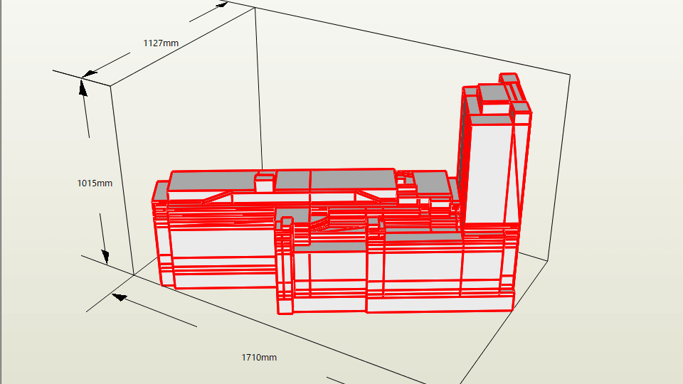
1.0147m = 1014.7mmTherefore, in "Specify assembled size", set "height" 1015mm If you set it to , the height will be 1/150 scale.
When you enter the "height", the "width" and "depth" will be automatically calculated based on the ratio.
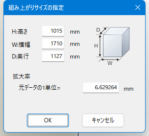
This method allows you to set the exact 1/150 scale architectural model size based on the height obtained from Google Earth while preserving the shape of your current 3D model.
3D model to development diagram
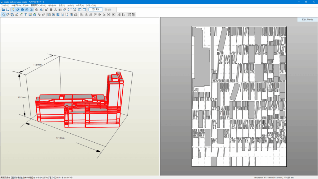
ここまで来たら、次は 3Dモデルを実際に展開図へ変換する操作を行います。画面上部のツールバーを見ると、「展開」というボタンがあります。
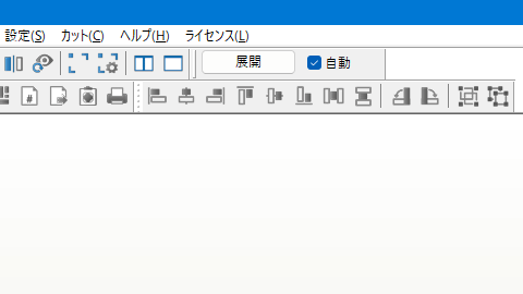
まずこの「展開」をクリックします。すると、Pepakura Designer が3Dモデルの面を自動的に分割し、右側のページにペーパークラフトの展開図を生成します。数秒待つと、右側の白い用紙エリアに建物のパーツが並びます。
Remove the overlap
When you unfold a 3D model, a development drawing with "surface margins" is automatically created by default. Therefore, we will hide the surface margins from the development drawing.
To do this, open the "Unfolded View Window (E)" from the top menu and uncheck "Show overlap (F)". This will remove the overlap displayed in the unfolded view, leaving only the outline of the part.
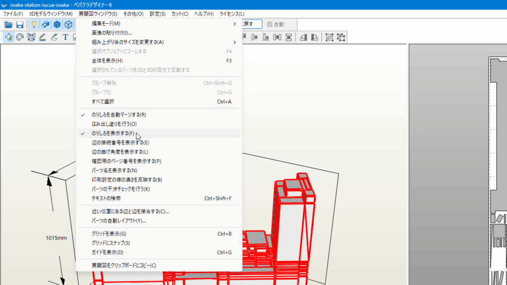
In normal paper crafts, the glue tabs are necessary for gluing parts together, but when it comes to architectural models or data for laser cutting, creating an unfolded view of only the outline makes subsequent work easier.
DXF Export
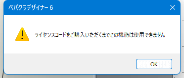
To use the file export feature, you need to purchase a Pepakura Designer license code.
Exporting files
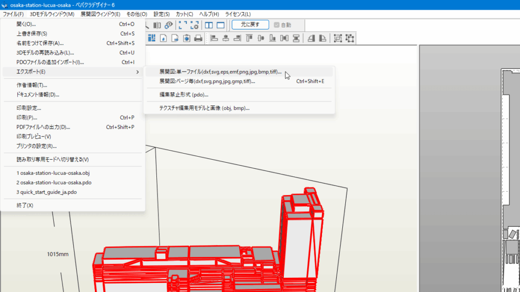
Once the development diagram is displayed, export the data as vector data for the laser cutter. Select "Export" from "File" in the top menu and save it as "Development diagram: Single file."
When exporting DXF, it is best to select "Unfolded Drawing: Single File." This is because, assuming you will be editing the unfolded drawing in vector editing software such as Inkscape, it is easier to handle if all parts included in the unfolded drawing are in one file. If you export it as a single file, you can check all parts at once when you open it in vector editing software, and you can adjust the position of parts, edit lines, delete unnecessary lines, and so on all at once.
This concludes the explanation of "How to use Pepakura Designer."